ProjectExplorer 4 for Autodesk Civil 3D
Tutorials | Generating AutoCAD Tables
Tutorials
Generating AutoCAD Tables
This tutorial demonstrates the use of ProjectExplorer to place two AutoCAD tables into a Civil 3D drawing. The first table will contain a simple Civil 3D alignment/profile report. The second table will contain a Pipe Run Report derived from a Civil 3D pipe network.
Getting Started
In Autodesk Civil 3D, Open the standard Civil 3D sample drawing: Intro-1.dwg
This drawing is part of the standard Civil 3D installation, and can generally be found in the following folder:
C:\Program Files\Autodesk\AutoCAD 2018\C3D\Help\Civil Tutorials\
Preparing to generate an AutoCAD Table
We can right-click any listed item in the ProjectExplorer window to access the AutoCAD Table creation options. Let's start by placing an alignment/profile report into our first AutoCAD table:
- From the Civil 3D ribbon, select the Add-Ins tab and open the ProjectExplorer window.
- From the Alignments tab of the ProjectExplorer window, locate the alignment Second Street, and right-click the associated profile: Finished Grade Centerline - Second Street Design.
- Select Quick Report to AutoCAD Table from the right-click menu.
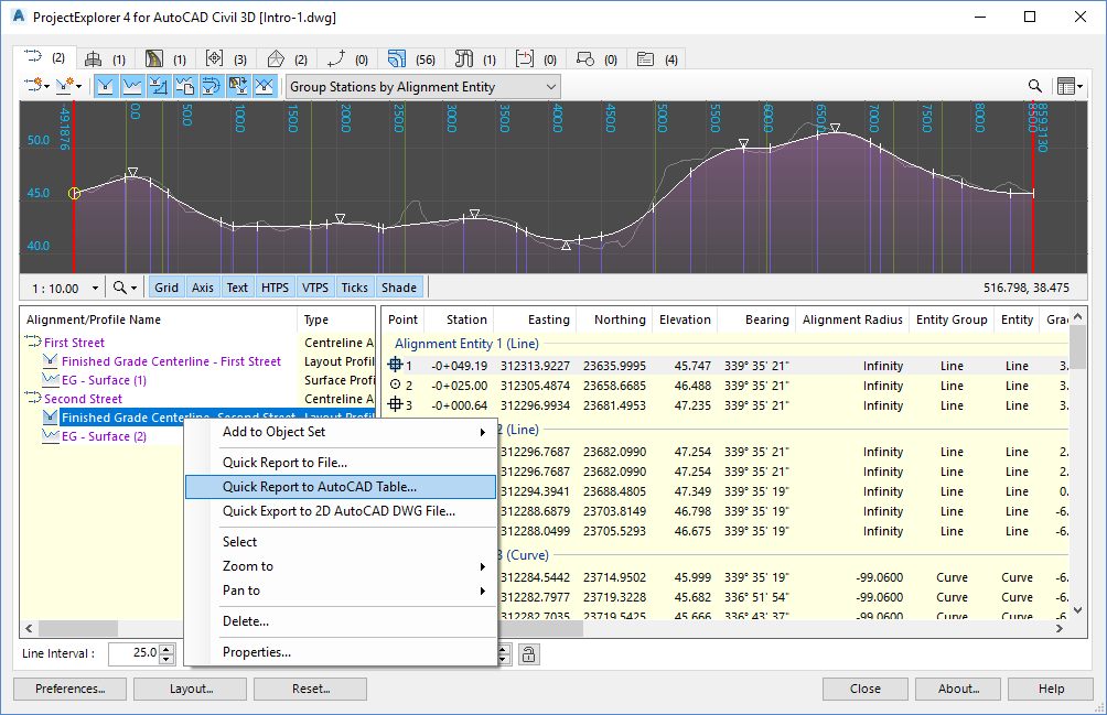
The Create AutoCAD Table dialog opens.
Configuring the AutoCAD Table
To generate an AutoCAD Table we need to configure the content, layout and style of the table using a Layout Style and a Table Style.
Layout Styles define the heading, visibility, and order of every column of data in the AutoCAD Table. The units of numerical values can also be controlled from a Layout Style.
Table Styles define the line color, text size and color, font, and cell margins for generated tables.
Layout and Table Styles can be saved and retrieved at any time, but for this tutorial we will define our requirements manually.
Layout Style Options
Change the Layout Style setting to Use a Custom Layout Style, then press the Edit Layout Style button.
The Layout Options dialog opens.
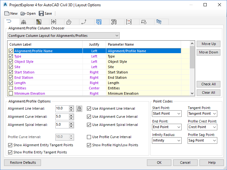
From this dialog we will define the layout of the AutoCAD Table.
- In the Alignments tab of the Layout Options dialog, ensure that Configure Column Layout for Alignments/Profiles is selected.
- From the list view, ensure that just the first seven columns are checked (Alignment Name, Type, Object Style, Site, Start Station, End Station, Length). We don't want to crowd our table with too many data columns.
- At this point, you may rename or reorder any of the selected columns to match the standards in your organisation. Columns may be renamed by double-clicking on the required label, or by right-clicking and selecting Rename from the right-click menu.
- Change the drop-down list in the Alignments tab to Configure Column Layout for Alignment Entities/Points.
- From the list view, ensure that just the following columns are checked (Point, Station, Easting, Northing, Elevation, Bearing, Alignment Radius, Entity, Gradient, Profile Radius, Profile Entity). Rename and reorder any of the selected columns to your own requirements.
- From the Alignment/Profile Options controls, set a desired Line, Curve and Spiral interval for the table.
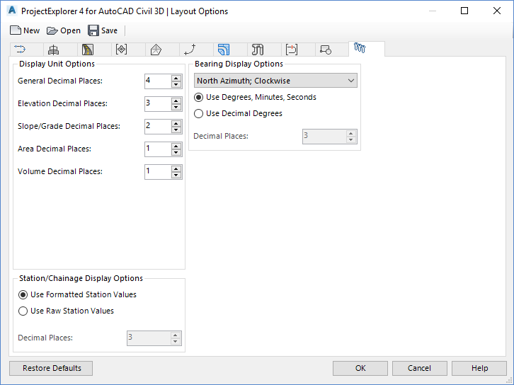
- Select the General tab and note the options here to set the format of numerical values such as angles/bearings, stations, elevations, and slopes. Changes applied here will only affect the content of the table.
Press OK to close the Layout Options dialog and return to the Create AutoCAD Table dialog. Next, we'll specify the style of the table.
Table Style Options
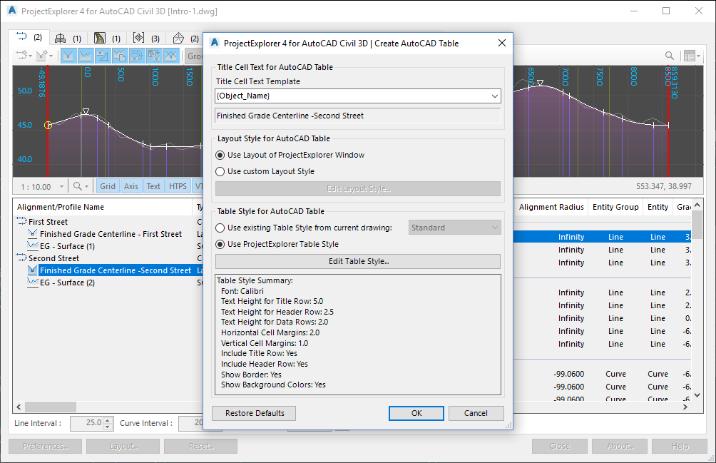
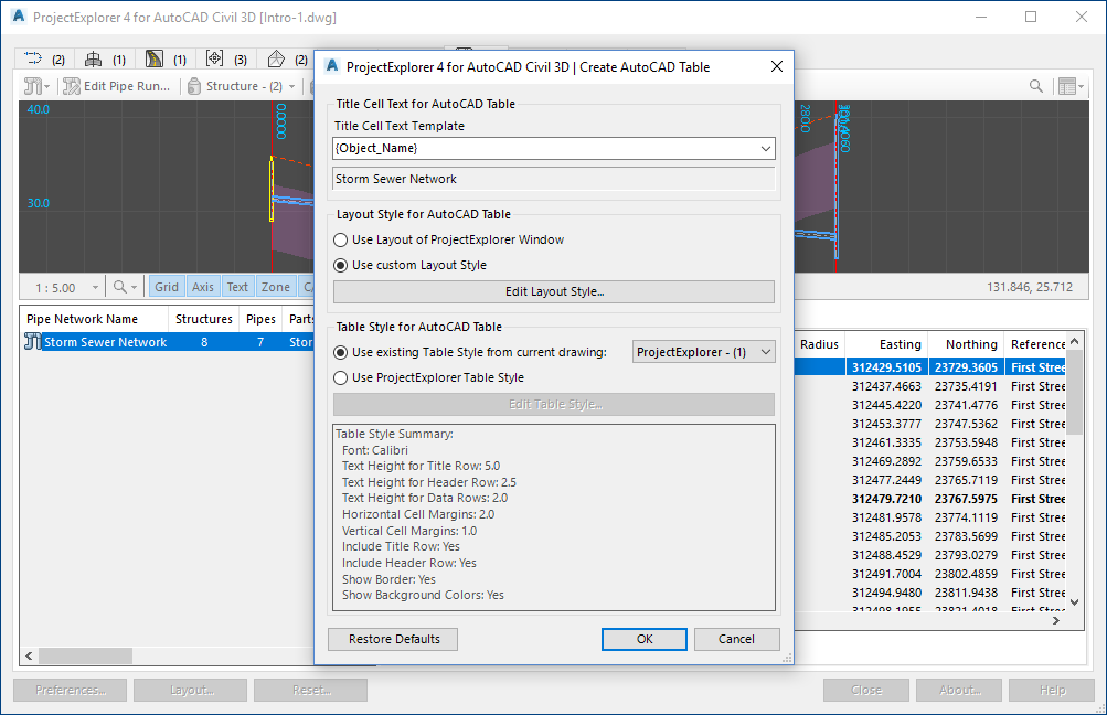
Back in the Create AutoCAD Table dialog, check that the Use ProjectExplorer Table Style option is selected then press the Edit Table Style button. The Table Options dialog opens. This dialog allows us to define what the table will look like.
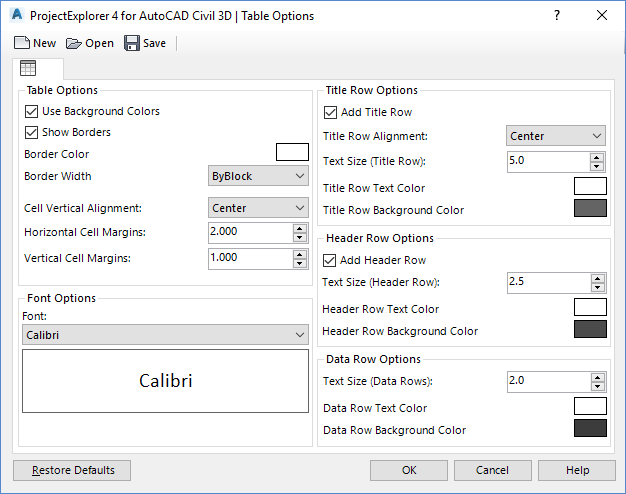
Set the table border color to Green, then modify other parameters of the table style to your own requirements.
Press OK to close the Table Options dialog and return to the Create AutoCAD Table dialog.
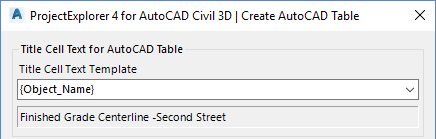
Title Cell Text
Note that the title row of the AutoCAD Table can be derived from a series of dynamic variables during the creation process, or you can specify a fixed file name in this dialog. By default, the title row will display the selected object name.
Generate the Table
We are now ready to create the table in AutoCAD.
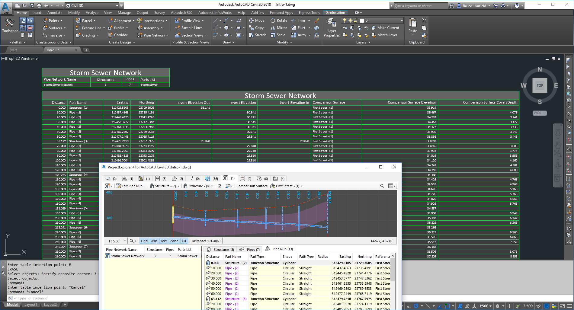
From the Create AutoCAD Table dialog, press the OK button and pick an insertion point in the AutoCAD viewport. The table is created.
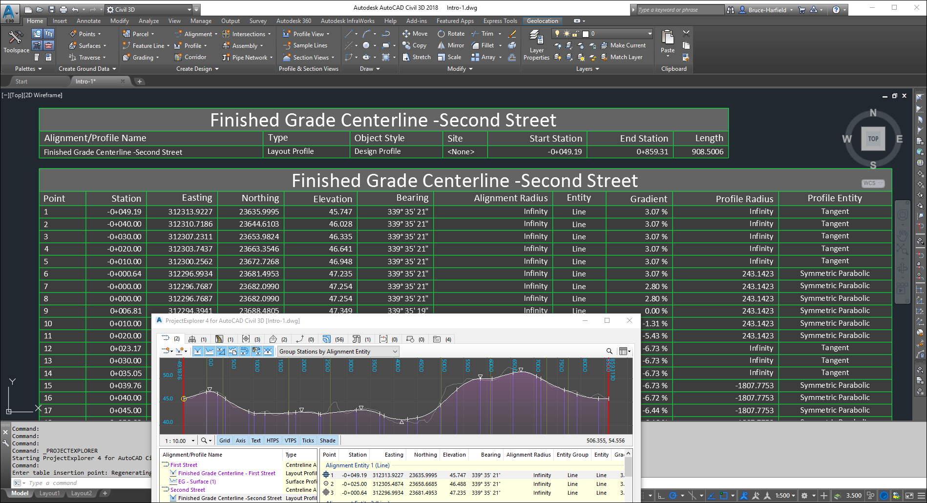
Note that two tables are generated, reflecting the content that you would normally see in the ProjectExplorer window:
- a header table featuring the basic properties of the object.
- a detail table featuring the station by station entity data for the alignment and profile.
If you wish to change the layout or style of the table, delete the table from the AutoCAD drawing and retrace the table creation steps described above. Your layout style and table style preferences will be remembered from the previous table creation session, and can be modified as required.
Placing a Pipe Run Report into an AutoCAD Table
Select the Pipe Networks tab in the ProjectExplorer window and locate the Pipe Network Profile Viewer at the top of the window. Select the Pipe Run tab as indicated below to preview the full pipe run details in the ProjectExplorer window.
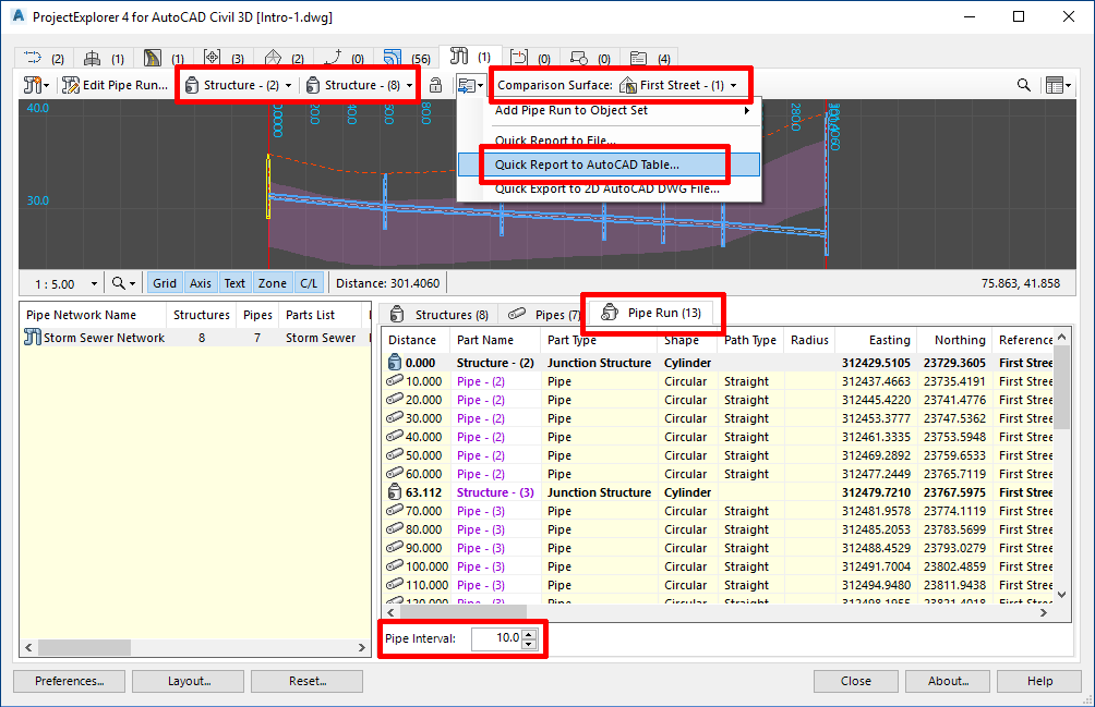
On the profile view toolbar, make the following parameter changes:
- Set the start structure to Structure - (2).
- Set the end structure to Structure - (8).
- Set the comparison surface to First Street - (1).
To start the process of creating the AutoCAD Table for this pipe run, press the Report or Export Pipe Run button from the profile view toolbar, and select Quick Report to AutoCAD Table from the drop-down menu.
The Create AutoCAD Table dialog opens.
Configuring the AutoCAD Table
Once again, we need to configure the content, layout and style of the table using a Layout Style and a Table Style.
Change the Layout Style setting Use custom Layout Style, then press the Edit Layout Style button. The Layout Options dialog opens.
Layout Style Options
From this dialog we will define the layout of content for the AutoCAD Table.
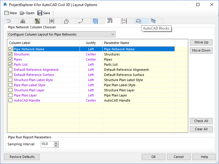
- In the Pipe Networks tab of the Layout Options dialog, ensure that Configure Column Layout for Pipe Networks is selected.
- From the list view, ensure that just the following columns are checked (Pipe Network Name, Structures, Pipes, Parts List). Once again, we don't want to crowd our table with too many data columns.
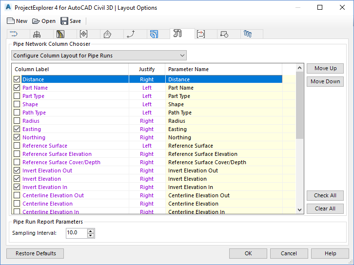
- Change the drop-down list in the Pipe Networks tab to Configure Column Layout for Pipe Runs.
- From the list view, ensure that just the following columns are checked (Distance, Part Name, Easting, Northing, Invert Elevation Out, Invert Elevation, Invert Elevation In, Comparison Surface, Comparison Surface Elevation, Comparison Surface Cover/Depth).
- Rename and reorder any of the selected columns to your own requirements.
- Optionally, choose your preferred sample interval to set the interval between points along the length of the pipe run.
Press OK to close the Layout Options dialog and return to the Create AutoCAD Table dialog.
Table Style Options
To re-use the AutoCAD table style which was created for the alignment table, ensure that Use existing Table Style from current drawing is selected, and choose ProjectExplorer - (1) from the list of existing table styles.
Generate the Table
We are now ready to create the pipe run table in AutoCAD.
From the Create AutoCAD Table dialog, press the OK button and pick an insertion point in the AutoCAD viewport. The table is created.
You have now completed this tutorial.